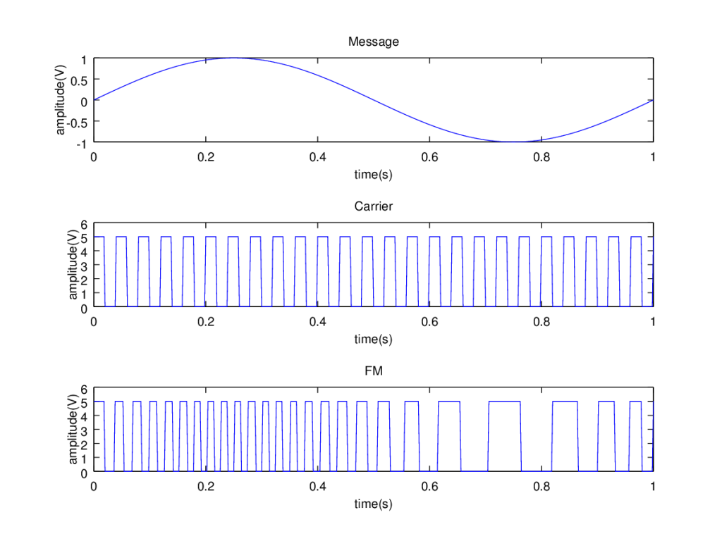
Frequency modulation is a common analog modulation technique. Here the instantaneous frequency of the carrier wave is varied with the instantaneous amplitude of the message signal. That is the information regarding the message is available in the frequency of the carrier. It is a kind of more generic technique called angle modulation.
 ][1]
][1]Gnu-octave has built-in function fmmod() available in octave-communications package for implementing frequency modulation. But this function modulates the given message signal with a sinusoidal carrier of specified frequency. If we want the carrier to be a square wave as shown in the figure, the built-in function would not help.
Let us see how this can be done. The carrier is a square wave. It may be represented as $$A_c square(\theta_c)$$. The angle modulated wave has the information content available in the angle part ($$\theta_c$$) of the carrier. When the carrier is angle modulated, the instantaneous value of $$\theta$$ depends on the message signal.
$$FM=A_c square(\theta_{i}(t))$$
The angle is not a constant. It varies with time depending on the message signal. In case of frequency modulation, the instantaneous value of that angle is the integral of instantaneous frequency of the modulated signal. Assume $$\omega_i(\tau)$$ is the frequency in radians per second and $$f_i(\tau)$$ is the frequency in Hz.
$$FM=A_c square(\int_0^t\omega_i(\tau)d\tau)$$
$$FM=A_c square(2\pi \int_0^t f_i(\tau) d\tau)$$
The instantaneous value of this frequency $$f_i(\tau)$$ is the sum of the carrier frequency $$f_c$$ and the frequency change due to the message signal amplitude. Assuming $$x(\tau)$$ is the unit normalized message and $$f_{dev}$$ is the maximum possible deviation from carrier frequency $$f_c$$.
$$FM=A_c square(2\pi \int_0^t(f_c+f_{dev}x(\tau) d\tau)$$
$$FM=A_c square(2\pi f_ct+2\pi f_{dev}\int_0^tx(\tau)d\tau)$$
To code the same in octave, each continuous time signal is assumed to be sampled at high sampling rate to obtain corresponding discrete time signal. The sampling frequency $$F_s$$ is kept high to avoid improper interpolation of signals while plotting them. Built-in functions can be used to define sine and square waves. The key step is in defining the modulated signal. As per the above equation the message signal has to be integrated with respect to time. For discrete time signals the integration can be replaced by using cumulative sum cumsum() function. The integration is along time axis. This effect can be implemented in the code by dividing cumsum() by $$F_s$$. The plot() function can be used to display the result of modulation. See the code snippet below.